


 |
High Reliability 350A TLC Telecom Rectifier
Product Details:
| Place of Origin: | Shenzhen, China (Mainland) |
| Brand Name: | ESTEL |
| Certification: | ISO9001, CE, 3C, FCC, TLC |
| Model Number: | GPE48350G |
Payment & Shipping Terms:
| Minimum Order Quantity: | 1 |
|---|---|
| Price: | negotiation |
| Packaging Details: | carton/wooden case |
| Delivery Time: | 7-10 working days |
| Payment Terms: | L/C, D/A, D/P, , T/T, Western Union |
| Supply Ability: | 20,000 sets per month |
|
Detail Information |
|||
| Installation Mode: | Embedded In Cabinet | Output Power: | 18725W |
|---|---|---|---|
| Input Voltage: | AC220V | Application: | Mobile Communication ,transmission Equipment Etc |
| Input Frequency: | 45~65Hz | Power Factor: | 0.98 |
| Highlight: | TLC Telecom Rectifier,350A Telecom Rectifier,350A rectifier system for telecom |
||
Product Description
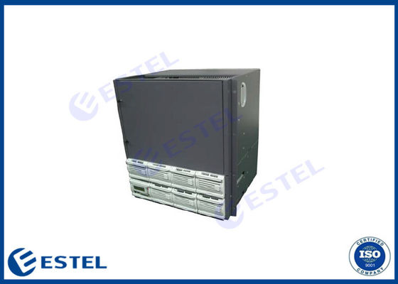
High Capacity High Reliability 350A Rack Mount Telecom Rectifier Embedded Power System For Outdoor Communication Cabinet
1. Application
(1) Small scale program controlled exchangers
(2) Access network
(3) Transmission equipment
(4) Mobile communication
(5) Satellite communication ground station
(6) Microwave communication
2. Feature
(1) Adoption of active power factor compensation technology with factor >0.98
(2) Wide operating range of AC input voltage: 90~290Vac
(3) Operating temperature range: -25°C~+55°C
(4) Zero current/voltage switching tech with high efficiency ≥91%
(5) Lifecycle of battery prolonged by perfect battery management, including electrical charge/discharge management, battery temperature compensation, battery capacity test, reversal connection proof protection, low voltage protection etc.
(6) Hot-swappable
(7) Input over/under voltage protection
(8) Output over voltage protection
(9) Output over current protection
(10) Output short circuit protection
(11) Auto current sharing, parallel output
(12) Embedded mounting
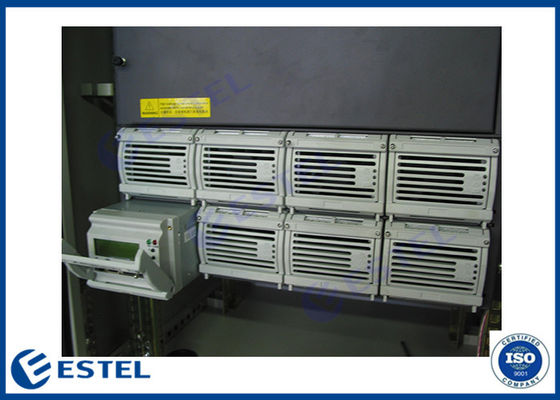
3. System Configuration
The system consists of power distribution unit, rectifier module (from 1 set, up to 7 sets) and 1 monitoring module. The configuration is optional, as following table:
| Configuration | Rectifier Module | Monitoring Module | Power Distribution |
| Standard | GPR4850D | GPM48P (With Ethernet Port) |
AC power distribution: single phase input, AC breaker @ general line (100A/2P); DC power distribution: battery 100A*4(fuse); LVLD: 63A×3 32A×5 16A×4 (MCB capacity optional) LVBD: 32A×3 16A×4(MCB capacity optional) |
4. Operating Principle
AC power is first input AC-INPUT MCB and then feed into the rectifier module after lightning proof and filtering. AC-INPUT acts as protection to over load and short circuit to AC power. The user’s battery is connected to the DC output side through MCB BAT and KM2, and the circuit breaker provides disconnection control, over-load and short-circuit protection to the battery.
Under normal conditions, every parameter of rectifier modules and power distribution unit are all under control of the monitoring module, operating according to the pre-set parameter or user’s commands. If AC mains faults, the battery will power to the system. With the battery discharge, the terminal voltage of the battery starts to descend. When battery voltage is under -47V±0.5V, the monitoring module sends DC under voltage alarm signal and when battery voltage is under -46.0V±0.5V (adjustable), the KM1cuts off non-priority loads and retaining power to priority loads. If battery voltage drops to -43.0V±0.5V (adjustable), the KM2 will cut off output of priority loads and then the power system will stop working. If the external AC mains recovers, the system will normally work again. (All above monitoring data are system default values and can be reset by user).
Except for battery over-discharge protection, battery or load over-temperature protection is prohibitive under default, users can send command to activate or inactivate according to the demanding.
5. System Properties
| Environment | |||||
| Item | Min. | Typical | Max. | Unit | Remark |
| Operating temperature | -25 | 55 | °C | When ≥55°C, decreased power output | |
| Storage temperature | -40 | 80 | °C | ||
| Humidity | 10 | 90 | % | Relative humidity without condensing | |
| Atmospheric pressure | 70 | 106 | KPa | ||
| Altitude | 0 | 3000 | m | ||
| Cooling | Forced cooling with fan | ||||
| Input | |||||
| Item | Min. | Typical | Max. | Unit | Remark |
| Input voltage range | 90 | 220 | 290 | Vac | |
| Input frequency | 45 | 50 | 65 | Hz | |
| Max. Input current | 40 | A | |||
| Power factor | 0.98 | Rated load | |||
| Input over voltage protection point | 300 | Vac | Automatically recoverable | ||
| Input over voltage recovery point | 290 | Vac | Return difference ≥5V | ||
| Input under voltage protection point | 85 | Vac | Automatically recoverable | ||
| Input under voltage recovery point | 90 | Vac | Return difference ≥5V | ||
| Input over current protection | MCB in AC Input supply protection | ||||
| Output (Table 1) | |||||
| Item | Min. | Typical | Max. | Unit | Remark |
| Output voltage | 42 | 53.5 | 58 | Vdc | Adjustable by monitor, tested in no load |
| Output power | 18725 | W | 18725W output when input voltage is 176~290VAC (rated power includes battery charging power plus load power) | ||
| 9350 | W | 90~175VAC input | |||
| Output over voltage protection point | 58.5 | 60.5 | Vdc | Lock up | |
| Output current limiting protection point | Output current limiting protection | ||||
| Output short circuit protection | Long-term short circuit protection, automatically recoverable | ||||
| Over temperature protection | Automatically recoverable in ambient temperature lower than 65°C | ||||
| Battery power-down protection | Battery power-down protection | ||||
| Battery polarities reversal connection protection | No damage on battery and power system | ||||
| Voltage regulation accuracy | ±1 | % | |||
| Output (Table 2) | |||||
| Item | Min. | Typical | Max. | Unit | Remark |
| Temperature coefficient | ±0.2 | ‰/℃ | |||
| Current sharing unbalance | ±5 | % | Within 50~100% load range | ||
| Start-up/shut-down overshoot range | ±5 | % | Any module is removed when operating, (the load current should be less than total output current of working rectifier modules), the system output voltage fluctuates | ||
| Dynamic response recovery time | 200 | uS |
25%~50%~25% load variation 50%~75%~50% load variation |
||
| Dynamic response overshoot | ±5 | % | Rated output voltage, rated load current | ||
| Efficiency | 91 | 92 | % | 220Vac input, rated output voltage, rated load current | |
| 83 | % | 110Vac input, rated output voltage, rated load current | |||
| Start-up time | 3 | 8 | S | pre-current limiting is fitted with start-up output between rated start up input voltage and rated output voltage established period | |
| Pressure drop | 500 | mV | |||
| Peak-peak noise voltage | 200 | mV | |||
| Psophometrically weighted noise voltage | 2 | mV | |||
6. Mechanical Properties
| Mechanical specifications | |
| Dimensions (Overall) | as the following diagram |
| Weight(kg)(Overall) |
≤43.5kg (Inclusive of module) ≤25kg (Frame + Distribution, exclusive of module) |
![]()
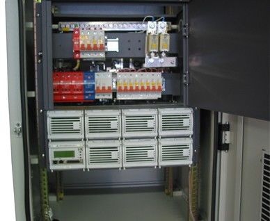
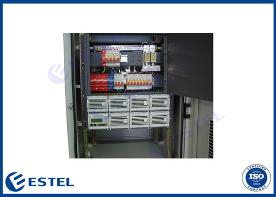
7. Electrical Connection
Chassis connects with external electric through system interface board. As shown in figure below:
![]()
MCB descriptions:
1. Single-phase AC input MCB and rail type connector;
2. AC SPD;
3. LOAD (-): system load- (7 MCBs,LVBD);
4. LOAD (+): system load+ and BAT (+): battery+ (copper bar at front of system)
5. LOAD (-): system load- (12 MCBs,LVLD);
6. BAT (-): battery- (fuse)
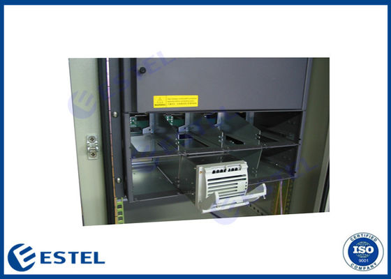
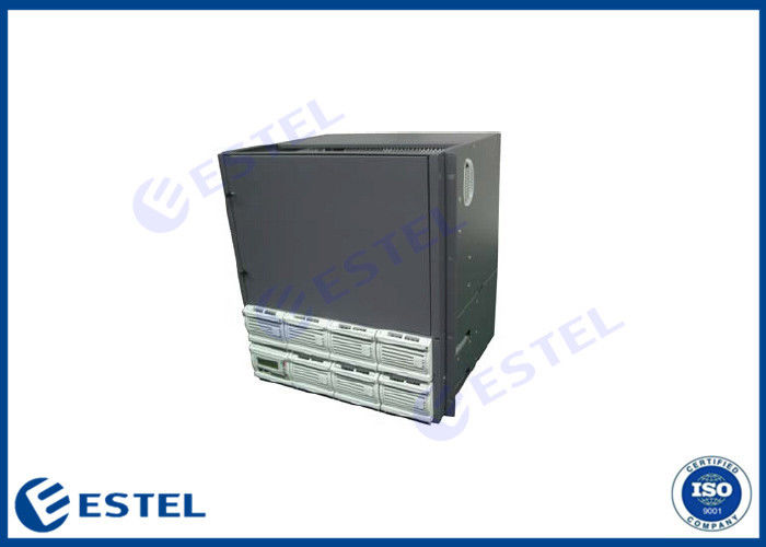
8. Product Pictures
![]()
![]()